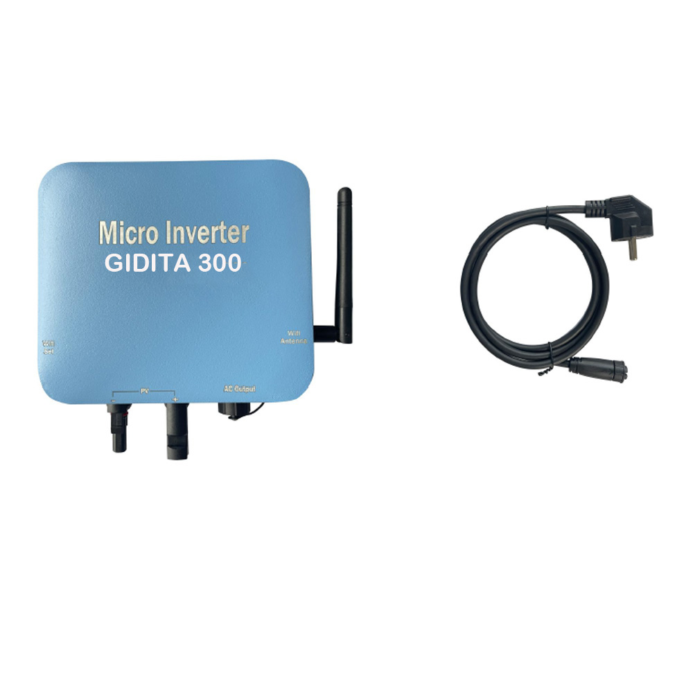
On Grid Micro Inverter WIFI With Cloud Monitoring Ip65 300W 350W 400W 500W
INSTALLATION PROCEDURES
*Prior to installing the Microinverters, Please verify that the utility voltage at the point of common grid connection matches the voltage rating on the Microinverter label.
Step 1 - Attaching the Microinverters to the Racking.
a. Mark the location of the Microinverter on the rack, with respect to the PV module junction box or any other obstructions.
b. Mount one Microinverter at each of these locations using hardware recommended by your module racking vendor.
Step 2 - Connecting the Microinverter AC bus cable one by one,
Step 3 - Connecting Microinverters to the PV Module, Please do NOT exceed PV panel(s) VOC over inverter max. input voltage.
Step 4 - Double check all Microinverters, connectors and cables are correctly and well connected.
Step 5 - Turn ON the main AC circuit breaker of utility-grid. Your system will start producing power after a 30secs safety delay period.
LED DISPLAY
1. Green light steady = Microinverter in generating.
2. Red flflash = Microinverter in waiting.
3. Red light steady =
a. Island protection.
b. Over-temperature protection.
c. Over / low AC voltage protection.
d. Over / low DC voltage protection.
e. Over / low AC frequency protection.
f. Fault.
WIFI LED Display
1. The green light flashes after always on = the WiFi cloud monitoring module is waiting for configuration.
2. The light off after always on = the WiFi cloud monitoring module starts and enters the normal working state.
3. The light flashes = the network is not configured or the network cannot connect to the wireless network device, or the micro inverter has been deleted in the cloud.
4. No light = WiFi cloud monitoring is working normally.


 Silver supplier


 Facebook
  Twitter
  Linkedin
  YouTube
  Blogger
  Instagram


